

|
Lafayette HE-80 General Coverage Shortwave Communications Receiver (1964) [Japanese Page] 
|
|
In the late 1950s the SSB became popular in the amateur radio voice communication.
SSB requires receivers with good frequency stability.
Good receiver shall have not only good sensitivity and selectivity,
but also further performance factors such as cross-modulation characteristics, good image rejection ratio and good S/N ratio.
Further, AGC characteristic shall meet the behavior of SSB signal. These requirements were too hard for single-conversion general coverage receivers, thus the amateur-band only, double-conversion receivers equipped with crystal filter became the mainstream, both in mass produced as well as home brew equipments. Meantime, Japanese amateurs had to wait for such next-generation receivers, until the year 1963, the debut of Star SR-600. The 1-RF 2-IF single conversion Lafayette HA-230 (Trio 9R-59) experienced considerable difficulties in SSB reception. The Lafayette HE-80 (Trio JR-60) was also a similar single-conversion general coverage receiver. However it had many enhancements over 9R-59 such as the use of voltage stabilizer, local oscillator buffer, product detector for SSB/CW reception and the Q-Multi functional also on SSB reception. Further enhancements were the crystal converter for 50MHz reception, FM demodulation capability and the built-in 100kHz crystal calibrator. How these enhancements would save the basic design of 9R-59? 2 years after the completion of the HA-230 restoration, a big brother HE-80 arrived at our lab. |
|
|
The Lafayette HE-80 is a 1-RF 2-IF, single conversion general coverage shortwave communication receiver utilizing 14 vacuum tubes.
It has 5 bands - 1 for medium wave, 3 for shortwave and 1 for the 50MHz band.
The lower half of the large lateral scale dial is a band spread dial, calibrated for amateur bands.
This receiver was designed and manufactured by Trio (later Kenwood), and put into the market in early 1964.
It was succeeded by HA-225 in December 1964. HA-225 appeared almost identical to the HE-80, however it had long wave band, instead of medium wave band. There are some detailed improvements inside. Some earlier production of the HE-80 had 144MHz (2m) crystal converter instead of 50MHz (6m), and had appearance identical to the Japanese domestic version, JR-60. |

|
|
The Lafayette HE-80 uses 14 tubes, the interior looks much gorgeous than the 9 tubes HA-230 (Trio 9R-59).
Out of these 14 tubes, one is for a 50MHz crystal converter and the other one is a voltage stabilizer.
So practically, 2 tubes are the pure addition to the HA-230.
These 2 tubes are used to make BFO and Q-Multi as independent blocks, and the addition of the product detector.
Therefore, if we look at the basic receiver design, it is still the 1-RF 2-IF single superhet,
just as same as the HA-230/9R-59. HE-80's power supply circuit is souped up than HA-230 in order to drive 14 tubes. It employs 6CA4 as a rectifier (whereas 5Y3-GY in HA-230). Although the miniature enveloped 6CA4 is smaller than 5Y3-GY, it can drive up to 180mA (whereas 125mA with 5Y3-GT). The high voltage windings of the power transformer though, has an marking of "DC110mA" - it would not overload the 6CA4. The most of the mid-class communications receivers in early 1960s used 5Y3-GY, bigger receiver used 5U4-G or 5U4-GB which was capable to drive 200mA. Later generation of receivers used silicon rectifiers. So receivers using 6CA4 were rather rare. The HA-230 has a power voltage selector switch choosing between AC100V and AC110V. It is omitted in the HE-80 and the AC power cables are connected to the AC110V winding of the power transformer. Here in Japan it is better to reconnect to the AC100V winding. A voltage stabilizer tube 0A2 (VR-150) is used in order to improve the stability against the power voltage fluctuation. The brute-forced way of thermal stabilization -- powering up the local oscillator heater all the time --- is not used in the HE-80. |
|
|
First let us take a visual inspection.
The outer appearance requires light cleaning, but there is no physical damage observed.
No missing parts, and the dial scale is in perfect condition - a good thing, as this dial scale decals could be peeled off very easily. Okay now pull out the chassis from the case... Hey! there is no screw! Screws which fix the chassis into the case are completely missing. It means the chassis was almost free inside the case, only 2 small M3 screws at the top of the aluminum front panel kept the chassis in place while the receiver was sailing across the pacific. Good packaging certainly helped. And perhaps the container box was not flipped over, as the box was quite large. Surface oxidization is obvious on the chassis, but no miserable rust. Underside of the chassis requires only light brushing to remove dusts. Components used are Japanese made quite typical to the early 1960s. Capacitors used in the RF stages are mostly disc ceramic, while tubular capacitors are used in the detector and AF stages. Replacing these capacitors are necessary. 6AQ5 tube, the audio power amplifier seems to have been replaced, but others are all Matsushita (now Panasonic) made -- seems to be the original. This indicates the run-hour of this receiver not so long. No obvious problem observed in the dial mechanism. Funny trouble is that the dial pointer derails from the guide rail and hitched to the dial wheel, when the main tuning goes leftward. After a quick diagnosis I connected a speaker and powered up the receiver. All the tubes and pilot lamps are illuminated, and the interior of the voltage stabilizer glows in fancy violet. Unexpectedly, no hum sound was heard. All controls show bad scratches, but a quiet and stable noise came from the speaker. Sounds as if the receiver is fully operational. Connecting an antenna, though, there was nothing received. Well, yes. It's not receiving at all, but the sensitivity is quite quite low. When I turn on and off the fluorescent lamp of the room I hear a spark noise, and actually the Radio Tampa, the Japanese only-one shortwave broadcast station was faintly received. When I turn the RF GAIN control to full up the volume goes rather low. The volume becomes maximum at the RF GAIN control slightly lowered from the full gain. Even so, the volume is quite low, and the sound is extremely distorted, and is quite dull and hollow. Speeches are barely readable. Okay, the receiver is in an ideal condition, to enjoy working on. Everything is tedious, if an equipment start working flawlessly right after purchasing it. Oh by the way, it was more than 6 years ago, but I found an interesting item on sale at a surplus shop Weired Stuff . It was a broken video tape deck, but it had a shiny orange sales tag, saying "Guaranteed Not Working; We'll refund if it ever works" - This shop knows the customer's need. |

|
|
As usual, until a service manual is obtained, I started to work on with the audio stage.
This receiver does not have a built-in loudspeaker. Speaker shall be connected to the screw terminal at the rear panel.
It has 3 terminals - a common ground, 8 Ohm and 500 Ohm output.
A regular speaker shall be connected to the 8 Ohm terminal. AF GAIN control is a ordinary volume control. The audio signal from here is amplified by the half of the 6AQ8, then further amplified by the 6AQ5, the power output amplifier tube. The audio output go through the output transformer, and drives the speaker. A headphone jack mounted on the front panel turns the speaker off when a plug is inserted. No resistor used for a headphone output. On the rear panel there is a recording jack. The output of the 1st audio amplifier is connected here. Feeding an audio signal into the volume control potentiometer, it was instantly obvious that the audio stages have a problem. Sound comes from the speaker, however the total gain of the amplifier is quite low. Mid- and high- tones are badly attenuated, just as if a good audio low pass filter is used. It is too much, even though the equipment is classified as a communication receiver. Firstly, without hesitation, the cathode bypass and plate bypass capacitors for output tube 6AQ5 were replaced with the new ones. These did not change anything. Next is to check the grid voltage of 6AQ5 -- oh my, it is more than 10V positive. The bias voltage obtained by the grid resistor would not be suffice to bring the grid to negative, with such abnormal grid voltage. It was the leakage of the coupling capacitor. The plate voltage of the 1st audio amplifier 6AQ8 went to the grid of output amplifier 6AQ5 through the coupling capacitor. Replacing it with a 0.01 uF film capacitor, the 6AQ5 grid voltage is now almost 0V. Frequency response improved a little. We go to the 1st audio amplifier, 6AQ8. Plate voltage of the 6AQ8 shows only 35 volts. Is this normal? B voltage is 135V. The plate resistor is 220 kOhm. So the plate resistor drops as much as 100V. This means the plate current is 45mA, which seems too much. Cathode bypass capacitor is a 10 uF type. Replacing this changes the cathode voltage from 0.6V to 1.0V. This capacitor should have been leaking. Frequency response of the audio stage is now very much improved. With music signal injected, cymbals and high-hats are sounding quite naturally. The grid of 6AQ8 is directly connected to the volume control potentiometer via a shielded cable. There is no fixed grid resistor. If DC voltage is applied to the volume control then it will affect the grid voltage. Hmm, is this okay? Now the high tone sounds natural and the total gain is much improved, still the audio quality is not satisfactory. It should be acceptable as an AM radio receiver, though, it is not good enough to listen to CD music. High tone becomes distorted, when a high-level bass drum tone is applied. This equipment is a communication receiver, expecting a good audio is a silly thing. Knowing that, let me experiment a little bit more. First, insert 0.1uF capacitor in the volume potentiometer hookup, and add a 220 kOhm resistor as a 6AQ8 grid resistor. Change the plate resistor from 220 kOhm to 100 kOhm, and change the cathode resistor fro 1.5 kOhm to 1.3 kOhm. This 1.3 kOhm cathode resistor is actually a series of 1 kOhm and 300 Ohm, adding a 10 uF bypass capacitor in parallel to the 1 kOhm. Further, the speaker output voltage taken from the secondary winding of the output transformer is connected to the 300 Ohm resistor via 3 kOhm resistor. This makes a negative feedback circuit. As a result, the total gain of the audio amplifier stage is now decreased. And the benefit is the improved audio quality - now the distortion in the high frequency when a strong bass drum imposed is negligible. It is now satisfactory for FM radio music programs. More than needed, or maybe too much, for a shortwave radio receiver. When the RF & IF stages becomes fully operational, and if the high-end is too hissing, then a shunt capacitor or something can be added to attenuate the high tone. I ask to myself, what is the difference between a loss of high tone due to an aged malfunction, and an intentional attenuation of high tone? |
|
| DESIGNATION | TYPE | USAGE | RESULT |
|---|---|---|---|
| C | 10 uF 50V | 6AQ5 Cathode Bypass | Replaced with 22 uF 50V. No difference. |
| C | 0.05 uF | 6AQ5 Plate Bypass | No difference. |
| C | 0.01 uF | 6AQ8-6AQ5 Coupling | Leaked. After replaced with 0.01 uF 250V, high-tone improved. |
| C | 10 uF | 6AQ8 Cathode Bypass | Leaked. After replaced with 10 uF 35V, distortion reduced, high-tone improved. |
| R | 220kOhm | 6AQ8 Plate resistor | Changed to 100kOhm. |
| R | 1.5kOhm | 6AQ8 Cathode Resistor | Changed to 1kOhm + 300 Ohm. |
| R (added) | N/A | 6AQ8 Grid resistor | Added 220kOhm as a grid resistor. |
| R (added) | N/A | NFB resistor | Adding 3kOhm resistor, NFB from OPT 2nd winding to the 6AQ8 Cathode. |
| C (added) | N/A | 6AQ8 Input coupling | Adding 0.1 uF 50V as a DC stopper. |
| C (added) | N/A | 6AQ8 Input bypass | Adding 0.022 uF as a high-tone bypass. (Mentioned later.) |
|
Audio stages are now thought to be fully functional.
Next is to work on the issue of losing audio volume, when the incoming signal goes strong. In HE-80, a diode detector by 6AL5 is used for AM reception, and a product detector circuit by 6BE8 is used for SSB/SW reception. The trouble is observed on both AM and SSB/CW. The receiver equips an ANL circuit. It becomes active when the FUNCTION switch is at ANL position (ANL not operational in SSB mode). The trouble occurs when ANL is not used. However, both the AM detector and ANL circuits are in the same envelope of 6AL5. It might be possible, that an inadvertent activation of the ANL circuit causes the distorted audio. However, this possibility can be eliminated, when we think that it occurs also in the SSB mode (where the product detector is used). Tracing the circuit diagram to learn how the IF signal is fed into the detector circuit. The intermediate frequency signal taken from the last IFT 2nd winding goes though a mica capacitor, and fed into the 6AL5 AM detector diode. It also fed to the product detector via another capacitor. One of them may have a problem which also causing to the other side - there might be such a possibility. So the capacitor to the product detector is disconnected temporarily. But no change. Viewing the AM detector diode output waveform with an oscilloscope, the basic diode detection is occurring. When a strong signal is applied, the peak of the waveforms are clipped. And when the signal gets more stronger, the audit output becomes silent. This is because even the most negative peak of the audio signal (the moment when the carrier amplitude became minimum) reaches the clipping level, thus no audio signal remains in the detector output. When the incoming signal is weak, or appropriately attenuated by going down the RF GAIN control, the demodulated audio becomes normal. Is this caused by the 2nd IF amplifier tube 6BA6 being overloaded? This seems to be plausible. In fact, the oscilloscope shows the 2nd 6BA6 plate voltage waveform being clipped at its peak, when the incoming signal is very strong. So the problem seems to be in the stages earlier than the detector stage. |
|
| DESIGNATION | TYPE | USAGE | RESULT |
|---|---|---|---|
| C | 0.01 uF Ceramic | 2nd IF Amplifier 6BA6 Input Bypass | Changed to Sprague 0.01 uF 80V. No change observed. |
| C | 0.01 uF Ceramic | 2nd IF Amplifier 6BA6 Screen Bypass | Changed to Sprague 0.01 uF 20V. No change observed. |
| C | 0.01 uF Ceramic | 2nd IF Amplifier 6BA6 Cathode Bypass | Changed to Sprague 0.01 uF 20V. No change observed. |
| C | 0.05 uF 600V Tubular | AGC Filtration | Changed to Nichicon 0.047 uF 400V. No change. |
|
AGC voltage is generated somehow as expected. DC voltage levels are in normal.
Temporarily replacing the tubes does not bring any change. 2nd IF 6BA6 screen bypass and cathode bypass were the ceramic capacitors, which are less likely to cause problems even after years. Capacitors in the 2nd IF amplifiers were replaced with new or NOS parts, but no change in the receiver behavior. The AC component of the 2nd 6BA6 plate voltage is not exceeding 30Vp-p, and its waveform is apparently clipping. Nevertheless no problem found in the IF amplifier or detector stages. This is puzzling! Tweaking around, nothing gave any clue. |
|
|
Locking paints were applied to all of the adjustment parts in the coil section, such as the coil core screws, trimmer capacitors.
And these locking paints, as well as the IFT adjustment screws, were broken.
This implies that at least one of the previous owners tried realignment.
It is better to see if these alignment was properly done.
Coil section shall be realigned after the audio distortion problem is solved.
So let us try the IFT realignment first. Remove the local oscillator tube 6AQ8, and inject the 455kHz signal generated by a signal generator into the 3rd grid (pin 7) of the mixer tube, 6BE6. Hook up a digital multimeter to the AGC line to monitor the AGC voltage. Also hook up the oscilloscope to the plate of the 2nd IF amplifier 6BA6. Trying realignment, it was found that all of three IFTs were aligned to their peak sensitivities. While tweaking around, I somehow began feeling something strange. It was when I tried to check the operation of the 1st and 2nd 6BA6. Hook up the signal generator to the 1st 6BA6 control grid, and I monitor its plate waveform with the oscilloscope. Naturally the plate waveform becomes maximum when the signal generator is set to the 455kHz. Trying the same thing on the 2nd 6BA6, of course the 455kHz signal gave the output peak on the plate. However, it was found that the approx. 370kHz signal gave another peak output, and that was much more stronger than 455kHz...!! The IFTs before and after the 2nd 6BA6 are now getting the attention. What's happening? While checking the resistances or possible short circuits of the IFT coil windings, I ventured to move the core adjustment screws for their full adjustment ranges. For each IFT, there are two points where the peak output is obtained. With the last IFT, I tried to search the other peak tune, then the detector input waveform went beyond the oscilloscope's screen! This is it! After the realignment, the detector input level is more than 10 times stronger than before. |
|
|
It seems that when the previous owner tried to realign the IFT,
he accidentally adjusted to the other peak point which is actually not 455kHz.
Both top and bottom screws of the last IFT were aligned to that "false" peak.
The output of the 2nd IF amplifier 6BA6 was largely lost before reaching the detector,
thus the AGC voltage was not much.
Without adequate AGC voltage the 6BA6 tube was driven with higher gain, caused the overload. After all, the problem of audio loss with strong signal was cured just with a screwdriver. Not only the audio loss problem was cured, the overall receiver sensitivity is now much better. Its performance is already far more superior than any 5 tubes superhet. Everywhere in the international broadcast bands are filled with stations and stations. When this radio was fired up for the first time, audio was so weak even with the AF GAIN full up. Now it shows another problem - audio does not go full silent even with the AF GAIN fully lowered. Should I feel happy with this? |
|
|
Either the output of the AM detector diode and the output of the product detector are selected by the FUCNTION switch,
then fed into the AF GAIN potentiometer.
Each output line has a DC blocking capacitor.
Therefore, the connection from the potentiometer to the control grid of the 1st audio amplifier does not need a capacitor.
However, both DC blocking capacitors were severely leaking.
The DC voltage applied to the potentiometer was plus/minus 1 to 2 volts in case of AM detector,
and more than 10 volts in case of the product detector - because of the part of plate voltage went though the leaky capacitor. As I wrote earlier, I had installed an additional DC blocking capacitor between potentiometer and the control grid, which made the problem caused by the leaky capacitor minimum. I replaced these leaky caps with new ones. No more DC voltage observed at the potentiometer. And a scratchy noise is now gone, which was heard when the AF GAIN control was operated in SSB/CW mode. |
|
| DESIGNATION | TYPE | USAGE | RESULT |
|---|---|---|---|
| C | 0.005 uF 600V Tubular - Mfg: Nichicon |
AM Detector Diode Output DC Blocking | Severely leaked. Replaced with Sprague 0.0047 uF. High range audio quality became improved. |
| C | 0.00 uF 600V Tubular Mfg: Nichicon |
Product Detector Output DC blocking | Severely leaked. Replaced with Sprague 0.0047 uF 80V. |
|
The AM reproduction audio quality is not yet satisfactory even after the works done until now.
It is acceptable as a shortwave communications receiver, yet it is not enough to enjoy shortwave broadcast listening.
The diode detector output waveform shows the upper peaks are truncated.
This behavior remains the same for various signal strength and volume control position -
so the detector stage is suspected. One possibility of poor audio quality is the AGC response being too quick. But this was not the case for now. 2.2 MOhm is used as the AGC resistor. Its actual resistance measured as 2.9 MOhm. This change, caused by the aging of the component, should make the AGC response even longer. Therefore this is not the cause of the audio clipping. I replaced the original resistor with two new 1 MOhm registers. The AGC behavior itself is quite natural and satisfactory, although the HE-80 does not have modern AGC circuit suitable to SSB - the fast attack and slow decay characteristics. Continue to seek the cause of poor audio quality, replacing other components, using another 6AL5, and even disconnecting the product detector. Still no luck. AM detection & ANL circuits using 6AL5 are well published, such as on the "Practical Vacuum Tube Handbook". The HE-80 AM detector circuit is slightly different from those published circuits. Is this audio quality a normal, with the HE-80 original design? In order to reduce AC hum in the detector stage, a 10 Ohm resister is series inserted to the 6AL5 circuit. Heater voltages of the other tubes are measured as AC6,7V, whereas the 6AL5 heater is driven by AC4.4V. Due to this reason the 6AL5 heater glows much dimmer than the others. Does this low heater voltage cause the audio quality problem? No, it doesn't. The audio quality remains the same, even when AC6.7V is applied to the 6AL5 heater, by shunting the 10 Ohm dropping resister. By the Practical Vacuum Tube Handbook says, it is better to ground the pin No.3, when one of the 5AL5 heater terminal is to be grounded. In HE-80, heater voltage is applied to the pin No.3 via 10 Ohm, and the pin No.4 is grounded. Will there be any difference if we follow the Handbook's recommendation? |

|
|
Coil pack alignment has not been performed yet, I wanted to check the overall sensitivity.
Connecting the signal generator output to the antenna terminal, and lowered the generator output.
When it goes weaker than 10 dBu, the signal is buried among the background noise and becomes unreadable. The shortwave reception environment of our lab is quite bad, so the stations I enjoy are the strong stations only anyway. Still, current performance of HE-80 is not acceptable. It is not because of the poor sensitivity, but because of the background noise is too high. The hissing noise does not stop when the antenna is disconnected. Where does this noise come from? Noise level is unchanged when the RF amplifier tube 6BA6 is removed. It is certain, that this is an internally generated noise. The noise level is higher than the other similar or identical receivers such as HA-230 or CRV-1/HB. Even further, the noise level is unchanged when the local oscillator tube is removed. HE-80 can receive FM signals. The noise is similar to the FM blank noise. Does the FM reception circuit cause the noise? Removing the 6BL8 from the 50MHz (6m) converter board, the noise is unchanged. Further removing the Q-Multi 6AQ8 does not change the noise, either. Removing the last one, the mixer tube 6BE6, eventually stopped the noise. So, after all, is this pure converter noise? |
|
||||||||||||||||||||||||||||||
|
Another 6BE6 in stock generates the same noise as the original tube.
So this is not a problem of the tube itself.
The pentagrid mixer tube 6BE6 is famous with its high converter noise, but is it such noisy? Voltage measurement result is as shown, looks normal. When the 1st grid and 3rd grid of 6BE6 are disconnected and kept open, noise level is decreased, but still exists. Wiggling the wire connecting the plate and the 1st IFT makes the noise level changing slightly. Q-Multi is connected here. Noise level is decreased when the Q-Multi circuit is disconnected. However, HE-80 would be no longer the HE-80 if Q-Multi is removed. After all, this may be the "normal" converter noise. And if this is the case, fundamental improvement would be to stop using pentagrid mixer, and to use triode mixer. Shall I try someday? Most effective countermeasure against the converter noise is to make the incoming signal always exceeding the converter noise. So, as an easy mod, I removed AGC line from the RF amplifier 6BA6, so that the RF stage is always in full gain. S/N ratio seems to be improved for the signals in moderate strength. For extremely strong signals from nearby peninsula and continent, overloading is obvious. Reducing the RF gain can easily solve the overloading. And this mod is quote simple - only reconnecting one resister - and can return to normal anytime. If AGC is not applied to the RF amplifier, there would be less necessity to use 6BA6, a remote cutoff tube. Receiver construction articles on QST magazines in late 1950s to 1960s shows usage of sharp cutoff tubes such as 6DC6 or 6AK5. These are to avoid poor intermodulation problem associated to the remote cutoff tubes. So I tried 6AU6, a sharp cutoff tube with same pin assignment as 6BA6. For international broadcast stations with good signal strength, the audio sounds better with lesser background noise. Not so dramatic difference, though. |
|
||||||||||||||||||||||||||||||
|
The S meter circuit of HE-80 is so arranged to read the cathode voltage of the 2nd IF amplifier tube 6AU6.
The reference voltage is derived from the screen grid voltage of that tube with adjustable voltage divider. In case of HA-230, S meter is connected to the 1st IF amplifier tube. This is because the 2nd IF amplifier is not AGC controlled in HA-230. In case of HE-80 the 2nd IF amplifier is also AGC controlled. The IF GAIN control of HA-230 changes the cathode resistance of 2nd IF amplifier. Therefore the S meter zero indication is affected by the setting of IF GAIN control. The RF GAIN control of HE-80 does not affect the zero indication of the S meter. The S meter used in HE-80 is same as the HA-230 - a vertically moving radicator. In the HE-80, the indicator is at the bottom when the power is off or when there is no input signal. As the incoming signal goes stronger, the indicator goes upward. This movement is opposite to the HA-230. Together with the S meter behavior when the RF GAIN is dropped, I prefer the S meter of HE-80 than HA-230. In this HE-80 the S meter itself and its corresponding circuit are working fine. However, previously mentioned modification - making RF amplifier always in full gain - makes the AGC voltage goes much higher (to negative) even with tha same incoming signal strength. This results in the S meter deflects fully almost all the time. The original meter series resister is 1.5 kOhm. By adding another 2.2kOhm resister (making the series resistance 3.7 kOhm in total). the S meter indicated S9 when the incoming signal strength is 40dBu. Strong signals such as VOA or BBC indicate S9+40dB on the s\S meter, the indicator deflects almost 100%. Perhaps this is the good setting of the S meter as a nice accessory. |
|
|
Realignment of the coil pack went successful for almost entire dial coverage for all bands.
Dial calibration is satisfactory. Shortwave sensitivity is just wonderful.
Audio power output is far more than plenty. VOA can be listened even the RF GAIN fully decreased.
It is so dramatic revival, when I recall the faint performance when the radio arrived at my lab. With the band selector at full clockwise, a 6m crystal converter becomes operational. Hooking up a whip antenna to the 6m antenna terminal, some noises are heard. I have no signal generator capable to output 50MHz range so accurate test cannot be done, however, the 2nd harmonic of 25MHz is heard on the HE-80, so I assume the crystal converter is working. If I pull out my Kenwood TS-60 stored somewhere in the lab, more test can be continued. |
|
|
The BFO circuit, which is used to receive SSB and CW signal, uses the 1st section of a 6AQ8 twin triode.
The 2nd section of the tube is used as 1st audio amplifier.
When the FUNCTION switch is at SSB-CW position, the cathode of triode is connected to the ground and the BFO begins oscillate.
BFO oscillator output is taken from the grid (pin 7), then directly fed into the 3rd grid of the 6BE6 pentagrid converter which works as the product detector.
Observing the waveform here, it is approx. 0V when BFO is not working. And it swings plus-minus 40V, with -50V at its center.
So the BFO signal is 80Vp-p.
Waveform itself is a clean sinusoidal, and is quite stable. BFO oscillation frequency was largely misaligned at first. Realigning the oscillator coil, SSB/CW are now demodulated clearly. Slow frequency drift exists and the frequency changes when a mechanical vibration is applied to the chassis. The frequency drift associated to the signal strength or power supply voltage is negligible. This stability was not possible on HA-230. BFO signal pull-in is existing. For example if you try zero-beating by using BFO pitch control, the demodulated audio level goes down, and becomes distorted. The BFO output, injected to the 3rd grid of the 6BE6, also appears on the 1st grid. This BFO signal on the 1st grid is then fed into the AM detector diode, detected, thus generating AGC voltage. Level of this AGC voltage is almost equivalent to S=9 incoming signal, and the S meter is always at S=9 indication. Result is, of course, lowered sensitivity. Therefore, to receive a weak signal, AVC-MVC switch has to be at MVC position, disabling the AGC circuit, and controls the RF GAIN manually. Adjusting the RF GAIN control changes the reception frequency slightly. To compensate this, BFO pitch control or the band spread tuning has to be touched again. After all, simple and easy tuning with single tuning knob is still a dream with HE-80. |
|
|
From upside and downside, severe QRM is always common in the 7MHz SSB phone band.
For such situation the Q-Multi comes to the rescue.
However on my HE-80, the Q-Multi is not responding. When the SELECTIVITY control is at full counter clockwise position the Q-Multi is turned off, and in this case the receiver is functioning normally. Once turn on the Q-Multi bu turning the SELECTIVITY control clockwise, the receiver sensitivity drops significantly, and the SELECTIVITY and FREQUENCY controls show no effect. Q-Multi is built in a sub chassis, and it has a Q-Multi coil. Tweaking an adjustment screw of this Q-Multi coil core does not show any changes either. A heater of a Q-Multi tube, 6AQ8, is glowing normally. Still the circuit diagram is not obtained. If I remove the sub chassis the circuit can be traced. But I assume its circuit is same as the HA-230, started to measure the Q-Multi tube voltages. |
|
| Measurement Points | Circuit Function | Measurement Result | ||
|---|---|---|---|---|
| Q-Multi OFF | Q-Multi ON (BROAD) |
Q-Multi ON (SHARP) |
||
| Rug board RED wire | Power supply to the crystal calibrator | When calibrator is ON: 88.7V }0.3V | ||
| Rub board BLUE wire | Q-Multi Tube Cathode | 0V | 3.3V | 2.45V |
| 22kOhm, opposite end to the Coax cable | Plate resistor B power supply | Open | 136.9V | 136.2V |
| 22kOhm Coax cable end | Plate Resistor, Q-Multi coil side | Open | 131.6V | 120.3V |
| 0.01 uF Switch side | Plate resistor, Q-Multi coil side | Open | 131.6V | 120.3V |
| Midget Tuning Capacitor Stator | Q-Multi tube plate | Open | 132.6V(*1) | 121.2V(*1) |
| 0.01 uF IFT side | IF signal line | 124V | 123.8V | 123.1V |
|
( *1: Voltage reading is slighly high as measured sometime later) ( Measured with the RF GAIN control at full counterclockwise. These voltages changes depending on the RF GAIN setting.) SELECTIVITY potentiometer is series connected to the Q-Multi tube cathode resistor, 3,3kOhm. When this control is at full counterclockwise, the cathode resistance becomes maximum, thus the Q-Multi tube is at minimum response. When the control is at full clockwise, the cathode resistance becomes minimum, which is 3.3 kOhm - the Q-Multi tube is fully working. At this setting the cathode voltage measured 2.45V. Thus the cathode current is approx. 0.74mA through the 3.3kOhm resistor. This cathode current should be equal to the plate current. Voltage drop by the 22 kOhm plate resistor measured 16V, therefore the plate current is approx. 0.72mA. These measurement result matches, within expected error. So, is this Q-Multi tube is actually amplifying? In case of HA-230 the Q-Multi becomes fully oscillating state when the SELECTIVITY control is full clockwise. But this HE-80 Q-Multi tube does not come to the oscillation. Is there any differences between them? Tried again the Q-Multi Core adjustment, the receiving audio shows changes. Ah, it is somehow working. Readjustment did not go smoothly if 455kHz test signal is directly injected from the signal generator. So the readjustment was done with real antenna signals. It did not work well when I tried for the first time, but now the receiver is responding to the readjustment, and it was completed. Summary: the Q-Multi problem was caused by previous owner's misalignment. 10kHz beat tone is annoying when international broadcast stations are to be heard. Q-Multi can reduce it considerably. Unlike HA-230, HE-80's Q-Multi can also be used for SSB/CW mode. In extremely congested 7MHz band the Q-Multi is helpful indeed, but less satisfactory. This may be because the HE-80's Q-Multi is designed not to going to oscillation. By adding 10 kOhm in parallel to the 3.3 kOhm cathode resistor, I modified it so that the feedback can be more strong, just before the oscillating point. Selectivity becomes much sharper just before the oscillation point, though, it is still not satisfactory for crowded band. Deterioration of the audio quality is also the drawback of strong Q-Multi. After all this is the limit of the Q-Multi -- due to its selectivity characteristic, having sharp peak and broader skirt. Yes, I know that. Otherwise, nobody build receivers with so many IF cans or costly crystal filters or mechanical filters, if one tube and a coil can solve the practical problem. Anyway the Q-Multi is now operational. This is a great advantage over the HA-230/9R-59. |
|
|
A Product Detector is a circuit which mixes the IF signal and BFO signal, and taking out the difference of two frequencies (called "heterodyne") to reproduce the audio signal.
Its principle is same as the frequency converter used in superheterodyne radio receivers.
In vacuum tube shortwave communication receivers, two most popular circuit arrangements of product detectors are; 1) Using three triodes (patented by Mr. M.G Crosby in year 1949) 2) Using a pentagrid converter |
|
|||
|
A book
Single Sideband for the Radio Amateur
shows an example of product detector using 6BE6.
Here the BFO output is fed into the 1st grid via capacitor,
and the book says make the oscillator amplitude to about 10V. Schematics shown left is an example in the Dempa Gijyutsu Shi (Radiowave Technology Magazine). BFO output is fed into the 1st grid via 100 pF, and the IF signal is fed into the 3rd grid. In another book Radio Handbook 16th Edition , an article "DX Communications Receiver", the BFO output is fed into the 1st grid via 10 pF. The circuit shown has a potentiometer which can adjust the BFO injection level. A famous article of home built receiver "HBR-8", designed by W6TC/SK, appearing on the March 1963 issue of QST magazine, the BFO output is fed into the 1st grid via trimmer capacitor. The article further suggests to adjust the trimmer so that the distortion of converter output becomes minimum. All of above article shows the BFO injection is on the 1st grid via capacitor, and the IF signal is applied to the 3rd grid. Common notation is that the BFO injection amplitude affects the demodulation quality. On the other hand the HE-80 injects the BFO output into the 3rd grid of 6BE6 (pin 7). Further its amplitude is approx 80Vp-p, sounds quite different from the recommended operation voltage for the 3rd grid, -1.5V, which is suggested by the RCA Receiving Tube Manual (RC-25). What was the intention of HE-80 design? |
 |
|||
|
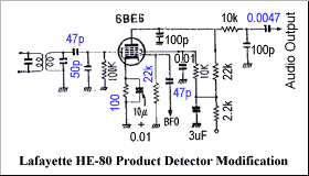
Tweaking the original HE-80 circuit does not bring any improvement,
I decided to venture modifying the product detector to the circuit shown right. 455kHz IF is fed to the AM diode detector via 100 pF, which is the same as the original. For the SSB/CW reception, the IF signal is fed to the 3rd grid of 6BE6 via 100 pF. The 3rd grid has a grid resistor of 100 kOhm (using the original component used for the 1st grid). 50 pF capacitor is arranged in parallel. BFO output is taken from the 6AQ8 grid in the way the original circuit, however it is injected to the 1st grid of 6BE6 via 47 uF ceramic capacitor. A grid resistor is 22 kOhm. The example circuit shown above uses 10 uF as a cathode bypass, meantime a circuit in the "Single Sideband for the Radio Amateur" says it would be from 0.01 to 0.1 uF. HE-80 uses 10 uF electrolytic and 0.1 uF ceramic are used in parallel. This 10 uF electrolytic showed obvious leakage, so I replaced it with a NOS Sprague. With rewiring completed, voltage of the 1st grid of 6BE6 is -11.5V in average, and the BFO amplitude is about 17Vp-p. On the 3rd grid, 455kHz BFO signal is observed with 2Vp-p amplitude. Screen grid is at 55V, demodulated signal and BFO signal are imposed. Cathode voltage is 0.83V. Since the cathode resistor is 100 Ohm, the cathode current is calculated to about 8.3 mA. So the operation result is... well, not a dramatic improvement. The sensitivity and the demodulation fidelity is obviously improved when the BFO frequency and the IF frequency is quite close, the BFO pitch control operation is far more smoother than before. Audio quality is also improved, but it is more prone to the overloading. Reducing RF gain solves this (there's a possibility of IF stage overload, though). Hissy noise became obvious when SSB is to be received. As a quick remedy, a bypass capacitor of 0.022 uF is added to attenuate the high tone. |
|
|
S meter deflects largely, even if the mixer tube 6BE6 is removed.
Waveform of the plate of 2nd IF amplifier 6BA6, 455kHz BFO signal is obviously existing.
The BFO signal is, not only via the interelectrode coupling within 6BE6, directly jumping into the IF stages.
Again, this is the reason of sensitivity degradation when the BFO pitch is at its center - due to the unwanted AGC voltage generated. Okay, so, how we can reduce jumping? Back to the SSB receiver design textbooks, in almost all of the SSB receivers, the BFO unit is constructed within a dedicated shielded container, and mounted onto the main chassis. BFO output is fed to the product detector by a shielded cable. In some examples, feed-thru capacitors are used where the B power supply wires enters the shield case. All these precautions are to reduce the unnecessary coupling to the rest of the receiver. This means, a big modification will be necessary to improve the HE-80 further. Good shielding of the BFO circuit is not only reducing the unnecessary coupling, but also to reduce the harmonics of 455kHz jumping into the RF stages. The later model HA-225 has almost identical circuit architecture - a 6AQ8 tube works as BFO as well as a 1st audio amplifier, however, the 6AQ8 and BFO coil are mounted on a sub chassis. After all, the HE-80 was an incomplete, still evolving model towards better SSB receiver design. |
|
|
Unfortunately the AM audio quality problem has not been solved, cozy shortwave broadcast listening cannot be enjoyed with this receiver,
although its sensitivity is marvelous.
I wonder if this is a problem particular to my machine, or is it typical to HE-80/JR-60?
I shall resume improvement activity someday, after studying and learning much more. |
|