 |
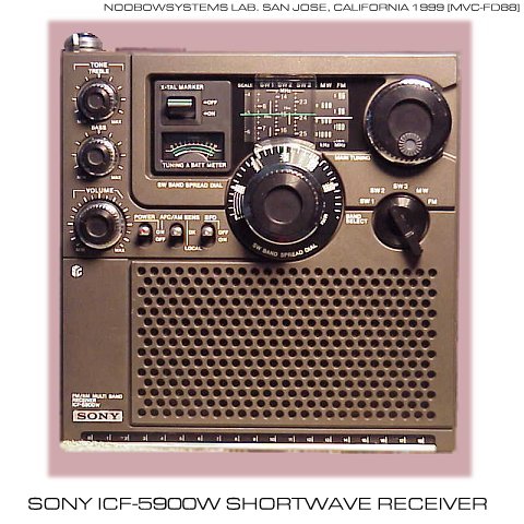
Sony ICF-5900W
General Coverage Portable Shortwave Receiver
The Masterpiece of Japanese Portable in the Middle 1970s
|
|
No explanation of this radio may be necessary for Japanese shortwave fans -
This is an export version of the famous
Skysensor 5900.
Unlike Japanese version,
it covers FM band from 88 to 108MHz. When I was an elementary school boy, several months of delivering milk bottles in the early morning allowed me to get money for my own shortwave receiver. Then the biggest problem in my life ever arose --- whether I should buy a Panasonic RF-2200 or a Skysensor 5900. The decision whether I should marry to this lady or not, was much quicker and easier choice than that. 5900 with crystal marker and bandspread, while linear-frequency tuning cap and two speed reduction tuning in 2200 ---- after weeks of wondering about, I chose 2200 which precise mechanism appealed to me. Literally I enjoyed 2200, days and nights. But after a year or so, my 2200 suffered several troubles. Most annoying thing was the backlash of the vital precision tuning mechanism. It was caused by my misuse; I accidentally applied mechanical shock to the dial knob. Backlash more than a few kHz really spoiled the pleasure of the shortwave adventure. Another trouble was that when listening 7MHz SSB amateur band the opposite sideband was too strong than desired sideband (possibly caused by the BFO frequency misalignment), I may be able to do something for it now, but an 11 years old kid never knew what to do. Following story is a very typical to radio kids of that time; acquire a license and get on-the-air on the 6m SSB. I wonder where is my 2200 now.... |
|
Advanced DXers would consider the ICF-5900 as a beginner's radio,
but it was certainly a dream machine for radio kids in the middle 1970s.
And, such radio kids had limited knowledge that double conversion was something great.
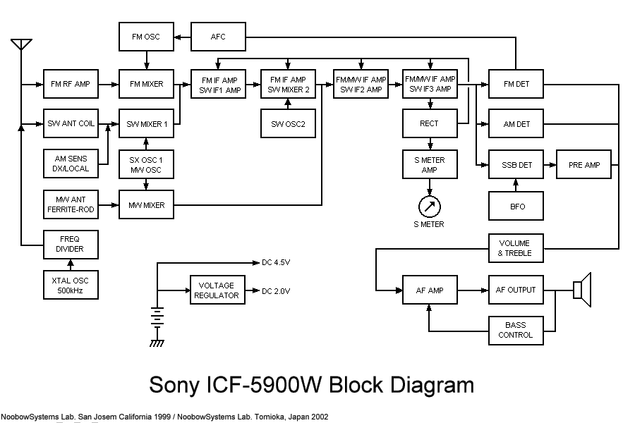
A quarter century later, a middle aged radio kid began reading 5900's circuit diagram with excitement. One of the sales pitches of the ICF-5900 was the double conversion system. Then the first question is how much is the intermediate frequency used. The answer is 10.7MHz for the 1st IF, and 455kHz for the 2nd IF. Hmm, 10.7MHz IF is identical to ordinary FM radios. Looking at the 5900's dial, we realize that 10.7MHz is in the band gap, i.e. between SW1 and SW2, and cannot be received. |
|
|||||||||||||||
|
In the traditional electrical bandspread arrangement,
i.e. having a small tuning capacitor in parallel with the main tuning cap,
the effectiveness of the bandspread tuning varies from frequency to frequency.
Therefore the bandspread dial can be calibrated only for particular portion of the shortwave frequency range. 5900's bandspread dial, however, provides constant cover range of plus minus 125kHz regardless of the main tuning setting. This enables to have the precise scale on the bandspread dial. Smooth reduction drive and 10kHz division scaling made "10kHz direct reading" possible, which was a dream before. How can this be achieved? The answer lies in the block diagram - the constant band spread arrangement. |
|
|
1st Converter and 1st IF Amp Incoming signal from rod antenna or external antenna terminal goes through the antenna tuning circuit which is tuned by the main tuning knob, and fed to the 1st mixer. There's no RF amplifier in this receiver. This mixer is a balanced type; 2 transistors are used. This configuration minimizes the local oscillator frequency leakage to the IF circuit. The 1st local oscillator is tuned by the main dial, and the 1st mixer outputs the 1st IF signal which frequency is approx. 10.7MHz. The signal is then amplified by the 1st IF amplifier transistor 2SC1908. Ceramic filters are deployed in the input and output of this transistor. This 1st IF amplifier also works as the 1st FM IF amplifier. It means that the bandwidth of these ceramic filters is same to the typical FM receiver; they are bandpass filters and do not provide selectivity required for the shortwave reception. Since the main dial of 5900 should be set to every 250kHz where indicated by the crystal marker, desired signal lies somewhere in 10.7MHz plus/minus 125kHz. Therefore, these filters should have a flat response for plus minus 125kHz. (The 10.7MHz filters used, however, do not have an ideal characteristic of such "flat-top"; causing the sensitivity variation within the 1st IF passband - this is described later within this article.) 2nd Mixer and 2nd IF Amp Amplified 1st IF signal is fed to the 2nd mixer. The 2nd local oscillator frequency is varied by the bandspread dial. Okay, this is why the bandspread dial gives a constant coverage, regardless of the band and main tuning setting. The 2nd local oscillator employs one transistor, and the bandspread tuning capacitor is in parallel with a local oscillator coil. When the X-TAL MARKER switch is ON position, bandspread tuning cap is substituted by a trimmer capacitor, eliminating the necessity to return the bandspread dial to zero every time the main tuning is to be calibrated. The 2nd mixer produces the 455kHz 2nd IF signal, and it goes through the IF transformer which contains a ceramic filter. The signal is amplified by the 2nd IF amplifier stages, which consist of a transistor and the only IC used in the receiver. Shortwave selectivity is provided by the filters and a transformer in the 2nd IF amplifier circuit. This 2nd IF stage also serves as IF amplifier for FM reception. In this case the signal goes through the 10.7MHz ceramic filter, which is in parallel with the shortwave IFT. |
The designation of the transistor tells something.
Why Q22 is missing; voltage regulator was originally designed with 4 transistors?
Why MW mixer is Q27; possibly the other transistor also acted as MW mixer in the original circuit...
|
||||||||||||||||||||||||||||||||||||||||||||||||||||||||||||||||||||||||||||||||||||||||||
|
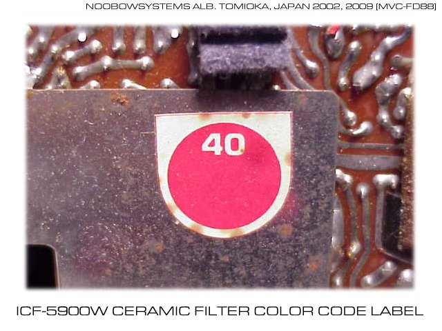
Ceramic Filters The interesting aspect of this shortwave receiver is that it uses the 10.7MHz ceramic filters for 1st IF stages. By using a component commonly available for FM radios, lower material cost could be achieved. Their center frequencies, however, vary from piece to piece. The 5900 uses 3 of those ceramic filters, therefore the filters used in a particular set must be chosen so that their center frequencies are close to each other. Sony production line prepared for 7 ranks of filters and adjustment procedure. Each ceramic filter had a color code mark which indicated its center frequency. All color codes of filters must coincide, and the center frequency applied to the set was indicated by a color label on the back side of the circuit board. My receiver has a red label, and the filters have red markings on their top, indicating 10.70MHz is the center frequency chosen at the time of production. |
 |
|
Detectors The output of the 2nd IF amp is always fed to three detector circuits simultaneously. These are the FM detector, AM diode detector and the product detector with BFO. When the band selector is set to FM, FM detector output is selected. When the band selector is MW or SW, AM diode detector output is selected if the BFO switch is OFF, and the product detector output is used if the BFO is ON. Selected output is fed to the audio amplifier. Pre-amplifier is used for the product detector output in order to equalize the audio level between AM and SSB reception. AGC voltage is generated by the AM diode detector, and is also used when the BFO is ON. The AGC time constant is unchanged whether the BFO is ON or OFF. AGC control voltage is amplified by a transistor and drives the tuning meter. SENS Switch 5900 has a SENS switch which has DX and LOCAL position. This switch may be used when a strong station is to be received, or to avoid the interference caused by strong adjacent signal. You might think this is a simple attenuator in the antenna circuit, but it's much fancier. A sensitivity control transistor is located between antenna tuning circuit and the 1st mixer. Normally the transistor is open and the receiver is in full gain. When the SENS switch is set to LOCAL, or the X-TAL MARKER switch is ON, base voltage is applied to the transistor and it shunts the incoming signal to the ground, thus the reduced gain of the receiver. This arrangement has a potential failure mode of poor sensitivity; if the shunt transistor failed with short mode, the overall receiver sensitivity remains low even if at the DX position. My unit is okay, but if yours has poor sensitivity and if it does not change regardless of the DX-LOCAL position, suspect the failure of the transistor Q26. X-TAL Marker The X-TAL Marker is used to set the main dial to every 250kHz position for example 15.000, 15.250. 15.500... MHz. The marker circuit consists of a 500kHz crystal and three transistors. Two transistors work as an frequency divider, providing 250kHz and its harmonics. Oscillator output is fed to the antenna circuit. The oscillator is powered up only when the marker switch is ON. The X-TAL MARKER lever operates a multi circuit slide switch, and it does many things with a single lever action;
Audio Amplifier and Output Selected output from FM detector, AM detector or the product detector is fed to the audio amplifier through the VOLUME control. The audio signal is amplified by two transistors and the final push-pull power amplifier which has a input- and output-transformer, drives the built-in speaker or earphones. Treble tone control is a simple shunt type attached to the VOLUME control. Bass tone control changes the frequency response of the negative feedback loop. Voltage Regulator 5900 requires three dry cells, thus the power supply voltage is 4.5V. As a portable but a high performance shortwave receiver, the radio must be stable against the battery voltage variation. ICF-5900 has a voltage regulator circuit which uses three transistors. It supplies stable 2.0V power to the voltage sensitive stages as follow:
The external DC power jack is outer-positive, center-negative. It is recommended to supply regulated 4.5V. The EXT TIMER IN jack is wired in series with the POWER switch. When no plug is inserted, this jack closes the circuit, thus the power can be turned on or off by the POWER switch. By connecting an external switch to this jack, receiver power can be controlled by that switch. If your receiver is completely dead, check if the contact of this jack is clean and they conduct properly. Inserting and removing a plug several times might make the contact fresh. |
|
The ICF-5900W I acquired was not perfectly clean, but seemed to have little trouble.
The only major and obvious problem was the missing battery cover (which is somehow common to surviving 5900s).
As long as the radio is placed on the desk it's not a big deal.
Pop-up antenna and LIGHT switch was in perfect condition, which is rather rare case.
Although the audio potentiometer was a little scratchy, no immediate service seemed to be necessary. Closer look revealed, however, the main dial was misaligned nearly 500kHz. This of course made the calibrated bandspread operation useless. I opened the cover, removed the film dial unit and reassembled again while monitoring the WWV. It looked that the previous owner had opened the cover many times so it was possible that he had misaligned the dial, but the aging might have caused it too. Another problem was the poor sensitivity at the high edge of the bandspread dial. It is said that this is a common problem to the 5900s so performing the full adjustment procedure may be necessary. Although the reception is good, too fast AGC response results in the noisy sound when the fading is severe. The plastic case is vulnerable to the external noise source such as computer monitors. Since my primary criteria today is to relax and enjoy BBC world service, the 5900 could not beat the Echophone EC-1A with external speaker, which has been occupied the prominent position in my lab. Nevertheless I feel very cozy and happy when this radio is at the corner of my sight. Take time, and let's enjoy the dream receiver for the radio kids in the middle 1970s. |
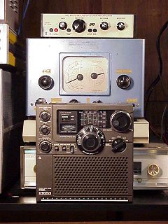 <ICF-5900W and Echophone EC-1A> |
|
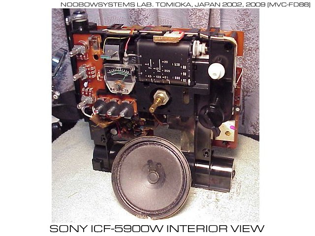
Removing the cover of 5900 is easy; all of the components are neatly mounted on the main chassis.
Engineers had learned more about the plastic design;
the main chassis shape is simpler than 5800,
and most of corners has round chamfer which helps the tooling life longer. The speaker used is 10 cm in diameter, and is glued to the plastic front panel. I removed the speaker from the panel in order to wash the front panel, and I found grains of sand on the speaker cone edge. Supposedly the radio was once used at a beach, or on a dune. sand grains entered through the speaker grill and were caught on the sticky residue on the cone edge. The single-side paper-epoxy printed circuit board has a cheap look. There are many sponge stickers to prevent rattle noise, but it also gives the poor sighting. Sony should not be blamed; after all, 5900 is a low priced, mass produced consumer product. |
 |
Result shows fairly good calibration. When the error reaches 125kHz, operator will have trouble calibrating the main dial to the marker signal which is 250kHz apart. Maximum error above was about 80kHz, not perfect but thought to be acceptable. |
|||||||||||||||||||||||||||||||||||||||||||||||||||||||||||||||||||||||||||||||||||||||||||||||||||||
 |
|
|
Flick the BFO switch ON, let's tune the dial to 14MHz amateur band.
Here in the very poor receiving environment of typical Japanese apartment house,
this plastic body receiver suffers from nearby computer and monitor noise,
the tuning meter never gets below half.
Tonight, however, several powerful DX stations are calling CQ Contest.
SSB audio is clear but slight chirp is noticeable in CW tone. Frequency stability is not perfect for SSB and CW, slow drift necessitates retouching the dial every 10 minutes or so in order to maintain the correct pitch. "Hands-off" reception is not possible with this low priced receiver, just as it was either not possible in the medium class vacuum tube general coverage communication receivers. Frequency drift trend measurement result is shown on the right. Condition was;
The overall performance for SSB/CW reception of this receiver is not perfect, but enough to explore the world of amateur and professional radio communication. |
|
|
The 5900 circuit requires many adjustments in order to achieve best operation.
If you attempt to perform realignment,
it is recommended to have the service manual which may be obtained from one of the manual copy services on the Net.
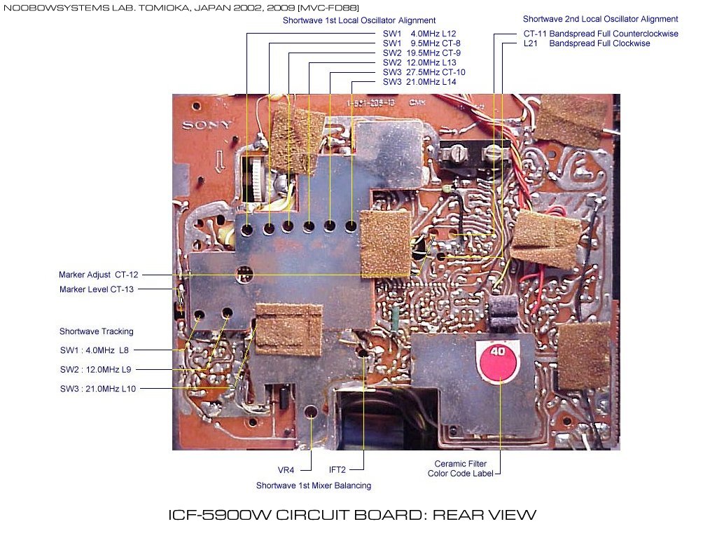
Following procedure is just my venture; I'll give you no warranty of correctness of the description. List of alignment items is shown on right. Phew. A small Adjustment Cover on the rear can be removed by loosing a screw. Underneath this cover, there are 6 trimmers for shortwave 1st local oscillator and 2nd local oscillator alignment. Most of the shortwave alignment can be done by removing the rear panel. To perform the full alignment, front panel must be disassembled. The unit in the lab showed sensitivity deterioration when the bandspread dial was at high position. The reason of the phenomenon was supposed to be the 1st IF filter center frequency shift. The unit had a red label on the PCB, indicated the 10.70MHz was chosen as the 1st IF center frequency when manufactured. |
|
|
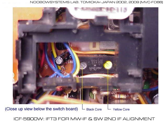
MW/SW 2nd IF Alignment The first step was to confirm that the IFT-3, located right after the shortwave 2nd mixer, was properly aligned. The designed 2nd IF frequency is 455kHz (468kHz for the U.K. version). The IFT-3 was hidden below the small switch board. By removing the board from the chassis, two cores of the Murata RFT455 IFT were accessible. I hooked up my signal generator to the 2nd mixer collector circuit, and applied 455kHz 30% modulated AM, with output level of 30dBu. Slight adjustment was necessary with the black core, to peak the signal. For the yellow core, peak could not be found with the signal generator signal. I disconnected the generator and peaked with yellow core, for the maximum background noise output. |
|
|||||||||||
|
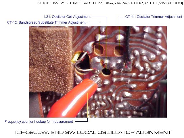
SW 2nd Local Oscillator Alignment The 2nd mixer should convert the 1st intermediate frequency to the 2nd intermediate frequency. Assume the 1st IF center frequency is 10.70MHz, the 2nd Local Oscillator must generate [ 10.7 + 0.455 = 11.155 ] MHz when the bandspread dial is at 0kHz. By connecting a frequency counter to the output of the 2nd Local Oscillator, its frequency was measured. When the bandspread was at 0 kHz position, the LO frequency was 11.1098MHz. Calculating 11.1098 minus 0.455, I got the 10.6548MHz as the center frequency currently adjusted. However this measurement might be inaccurate, because the frequency counter hookup would cause the detuning. |
 |
|||||||||||
|
Next, I disconnected the frequency counter, and hooked up the signal generator to IFT-2,
which is output of the 1st mixer.
Set the bandspread to full clockwise and counterclockwise, and tune the signal generator,
the 1st IF frequency actually received was measured. Seem like the receiver's center frequency was adjusted to 10.663MHz instead of 10.700MHz. Because this was approx. 40kHz lower than it should, the sensitivity dropped at the high end of the bandspread dial. |
|
|
|
Marker Alignment After the 2nd LO is aligned, the maker alignment must be performed. This has two different adjustments. The first thing to do is actually a bandspread substitute trimmer alignment. The next is the marker injection level adjustment. As described before, the bandspread tuning capacitor is substituted by a trimmer capacitor when the XTAL MARKER switch is ON. The capacitance of the substitute trimmer must be exactly the same as the bandspread capacitor at 0kHz position. This adjustment can be done by tuning CT-12 trimmer. This procedure requires the bandspread dial scale ring is assembled to the bandspread tuning shaft; i.e. front panel must be assembled. Set the bandspread to 0kHz position, turn on the BFO and set the signal generator to the 1st IF center frequency. Tune the generator so that the received sound becomes zero beat. Then, keeping the signal generator frequency, turn on the XTAL MARKER switch. Use CT-12 trimmer so that the received sound also gets the zero beat. When this is properly done, exact same frequency is to be tuned whether the XTAL marker switch is on or off. The next is the marker level adjustment. Simply, tune the receiver to 28MHz, turn XTAL MARKER on, and tune CT-13 so that the marker signal strength is approx. S=5 to 6 on the tuning meter. In my unit the marker signal level was nice S=5 at 15MHz where I prefer most, so I did not perform this alignment. |
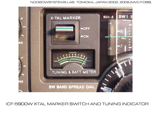 The "XTAL" marker switch. The tuning indicator hand rests on right edge when the power is off; i.e. opposite movement. Dial light can be turned on by pushing the yellow button on the top. However the brightness is just a joke. |
|
Shortwave 1st Local Oscillator Alignment (Dial Scale Alignment) Now the 2nd Local Oscillator has aligned to the new 1st IF center frequency, and the bandspread is calibrated. Now perform the 1st Local Oscillator adjustment so that the main dial scale can be properly aligned. Hook up the signal generator to the antenna terminal, set the band selector to SW1. Tune the generator to 4.000MHz, set the main dial to 4MHz, and turn the L12 so that the generator signal is to be received. Then set the generator to 9.500MHz, dial to 9.5MHz. Turn the CT-8 so that the generator signal is to be heard. Repeat this until the dial scale and actual reception frequency matches on both 4 and 9.5MHz. Same procedure should be repeated for SW2 and SW3 band, using frequencies and controls shown in the picture here. This adjustment went quite smoothly. |
 |
|
After the dial scale alignment, the readout accuracy became almost perfect.
Now we can listen to the moment when our favorite stations powering up their transmitter - welcome to the world of 5900! MOVIE CLIP: Tune to VOA at 15.150MHz
Engage the XTAL marker, zero beat to 15.250, disengage the marker.
Then simply turn the bandspread to -100kHz position to listen the VOA on 15.150kHz.
Tuning an exact zero beat may not be necessary unless you are a perfectionist; the spread dial already contains errors of 1kHz or so. MOVIE CLIP: Tune to WWVH at 15.000MHz
WWVH Hawaii is exactly on 15.000MHz readout!
Pay attention that the initial setting of bandspread is not at 0kHz when the XTAL marker is tuned.
This demonstrates the bandspread substitute trimmer is properly aligned.
|
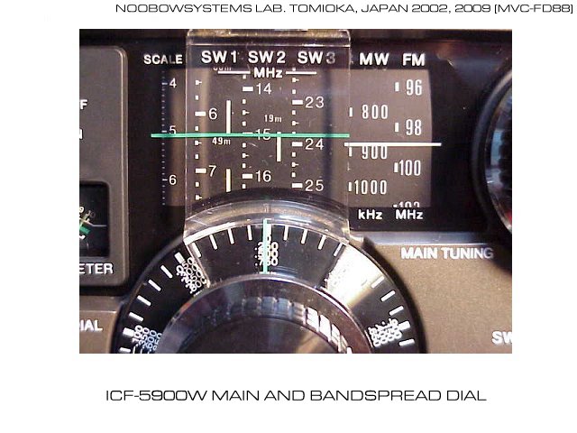
Boy this dial is really COOL. Modern digital models lack this beauty...
There are two versions for the bandspread dial scale ring. The unit here is the later production; 0kHz position is indicated as "0/.250/.500/.750". Earlier production had -125 to +125 indication. |
You may think the realignment result still contains error. But when I use this radio I usually look down into the dial, not moving my head to the same height of the dial. Having approx. +20kHz of intentional error is practically the best result for me. The sensitivity is good, however this is just another plastic body portable. It suffers the noise interference from nearby computers and monitors. Signal strength must be at least 10dBu or more to overcome the lab's ambient noise. If a 5900 with hopelessly miserable appearance, it will be fun and interesting to build a steel case communication receiver using its circuit board. |
|||||||||||||||||||||||||||||||||||||||||||||||||||||||||||||||||||||||||||||||||||||||||||||||||||||
|
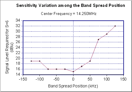
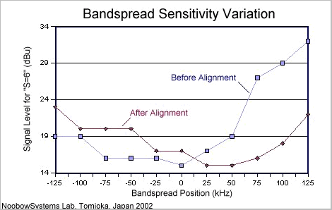
Signal level required for "S=6" indication was again measured for various bandspread positions. Result is shown here along with the before-alignment result. The graph clearly shows the effect of shifting the 1st IF center frequency. Still the sensitivity variation exists, however, its distribution is much better than before. Maximum deterioration is 8dBu, which has been improved from 17 dBu. |
|
|
||||||||||||||||||||||||||||||||||||||||||||||||||||||||||||||||||||||||||||||
|
Superior performance, marvelous styling and price affordable even to the radio kids -
ICF-5900 certainly drove kids in the middle '70s to the world of electronics and communications.
There's no wonder why the enthusiasm still persists with the 5900s in Japan and all over the world. Please share your story or valuable information such as restoration topics. NoobowSystem's Guest Book can be used as ICF-5900W discussion room . Please leave your comment, information, or any words regarding 5900. We have received many emails from all over the world, which I think many 5900 fans want to share. Guest Book can be accessed via NoobowSystems Lab. Homepage . We also want to have a link to your 5900 information. Please let us know your website. |
The 5900's logo, appeared in Japanese advertisements. SINPO55555-BCL RX clearly indicates the 5900's target market. Katakana characters above "5900" reads "SKYSENSOR", very famous name for the high performance SONY portables in the 1970s. |